MeshCore is a compact mesh networking stack. KDZU uses MeshCore for the New AfterLife Array project to send wireless messages to MIDI-controlled instruments. The New AfterLife Array is a set of four Heltec v4 nodes connected to raspberry pi computers.
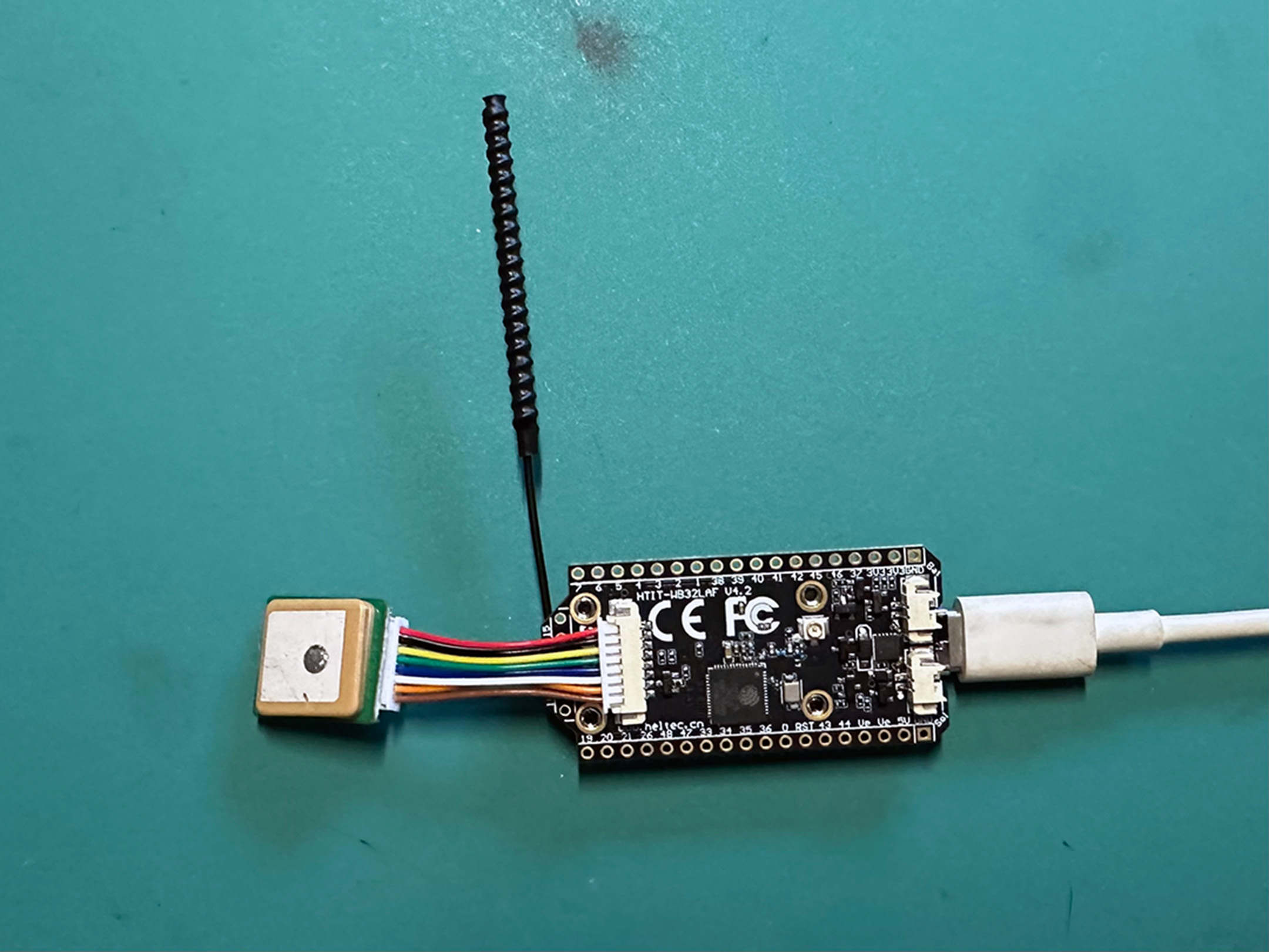
First Step: Connect the Antenna!
Always connect the antenna as your very first step before plugging anything in. Don’t connect the board to your computer. Don’t plug the battery pack in. Connect the antenna first, then have fun plugging things in.
The antenna’s IPEX MHF1 / U.FL connector is next to the little OLED display. These connectors are tiny and easy to bend. I use a magnifier to see the connector better. I use a little plastic flathead screwdriver to apply downward pressure on the connector to snap it into place.
Next steps
Flash the board with the latest MeshCore firmware
- Use a USB-C cable to connec the board to computer.
- Go to https://meshcore.io/flasher and select Heltec v4.
- Choose the Companion USB role. At the time of writing this will install the v1.15.0 firmware.
- There is a Flash button the left and a Download button. Flash! will flash your device. Download will give you the option to download the .bin files if you want to use a different flasher or keep a backup for safekeeping. Download if you like, then Flash!
- Your browser will open a pop-up saying meshcore.io wants to connect to a serial port. You’ll probably see a few options, pick USB JTAG/serial debug unit (cu.usbmodem1101). Windows users might see something slightly different. Find the port that looks like it is the Heltec 4 board and go for it.
You’ll see the board being flashed and you should get a result that looks similar to this. Watch the OLED screen on the board itself to see when it completes and restarts. You should see a message on the OLED displaying the new v1.15.0 firmware version and then the screen will go black.
Writing at 0x9d1b2... (92%)
Writing at 0xa51d2... (96%)
Writing at 0xaa712... (100%)
Wrote 657184 bytes (409576 compressed) at 0x10000 in 4.456 seconds.
Leaving...
Hard resetting via RTS pin...
Connecting the GNSS
Unplug the board from power and/or USB-C first before connecting the GNSS reciever board.
The Heltec v4 has a dedicated 1.25mm 8-pin GNSS interface for connnecting the GNSS (Global Navigation Satellite System) reciever that is included in the dev kit.
The connector is a little finicky but the GNSS cable should go in if you apply light pressure and wiggle it just a little bit.